The GAWWDAM Final Build - Part 2
- Joseph Scaglione
- Apr 5, 2023
- 8 min read
Updated: Nov 28, 2023

Building the "hot side" of the turbo system & Steering Shaft.
If you're not familiar with all of the components of a turbo system, take a few minutes to read the following post and learn how they work.
Unless noted otherwise, all tools and supplies I use in this post were purchased through Amazon. The full list on Amazon can be found here.
All of tubing I use for the hot side is Vibrant Performance mandrel bent stainless steel. The Turbine Inlet Piping is all 2.5" and the exhaust is 4". The V-bands and bellows are also Vibrant Performance. The Turbine Exhaust Flange is from Monkey Fab.
ALL of the cuts on tubing in this post were with my Fein Slugger Metal Cutting Chop Saw using an Evolution Cutting Blade made for stainless-steel.
Fitment of your tubing is crucial when are doing this type of work, and you will never get good fit up (or good overall results) without proper cutting. Before buying the slugger, I did try a harbor freight chop saw and it was truly horrible for stainless steel and aluminum tubing. this video shows a comparison.
The Billet T6 turbo flange and Turbo Mount were purchased from Maven Performance.
The Steering Column, Steering Shaft, and U-Joints were purchased from Motion Raceworks. The Manual Rack Kit is from PA Racing.
All Tig Welding supplies I used can be found here.
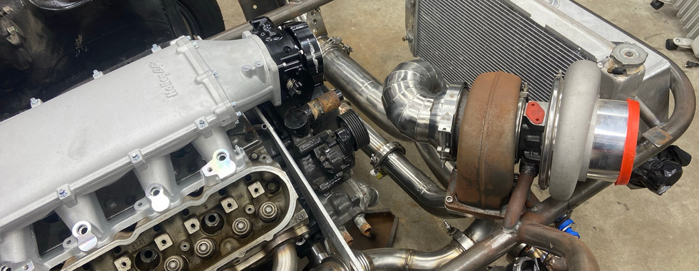
Building the Hot Side


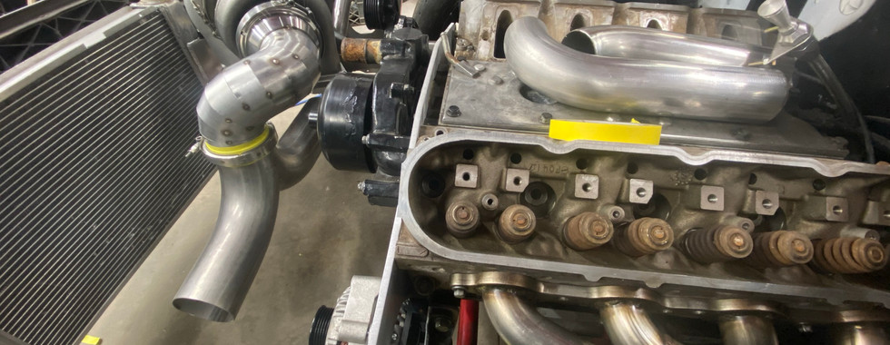
As soon as I started on the turbo kit, I ran into my first issue. At no fault to Mark, the turbo was mounted too close to the engine. I was set on the exhaust running out of both fenders. To do this, I'd need to build a reverse Y-Pipe to split 1-into-2. Those Y-pipes take up a bit of space when you're dealing with 4" tubing, so my plan was to mount it vertically in line with the existing hole in the passenger side fender. A crazy bend made out of pie cuts would be needed to connect the turbo exit to the vertical Y-Pipe and it ended up being too close to the water pump and belt. To clear the water pump, I'd have to move the turbo towards the front of the car. The hood slopes downward the further towards the front you go, so it would have to also be moved downward to maintain hood clearance.
Mark offered to help me get it all sorted out. He stopped by one night to do the final welding on the new mount after I had it set and tacked into place. The first two photos above show the turbo mounted in the original location, and the second two show it mounted in the new location. If I didn't point out the turbo moved in that series of photos, you probably wouldn't have even noticed. This is a perfect example of how crucial planning and placement of components are. Having to go back and move items is a ton of work and can really snowball into a series of necessary changes, so its worth taking the time to plan ahead and do it right the first time. As you can see, there was not much room for error to clear the front bar. Even moved down so close to the bar, the turbo ended up barely touching an inner support of the hood that will be trimmed later on.


With the turbo in its correct location, it was time to build the Y-Pipe.
To build the y-pipe, you need to start with a 180-degree bend. I used a U-J bend so I'd have the extra 45-degree bend left over to use elsewhere. You need to mark the center line of the bend (vertical line in photo above), and then use that as a reference to mark an intersecting center line of the tubing.
I drew it all out on the table to get those center lines. First, I set the bend flush & square with the bottom of the table and marked the outside lines using the tubing as a guide. Then, I removed the tubing from the table, drew a vertical center line between the outside markings, and a horizontal line 2" (1/2 of 4") above the bottom edge of the table. Finally, I set the tubing back in place and used my laser level to transfer the lines marked on the table to the tubing.
As you can see in the third picture, once you cut along the lines and flip the pieces together, you're left with a 1-2 merge that is 4" diameter all around (because center lines). After I cleaned up all of the cut edges, I tacked it together. I still wasn't feeling too confident in my tig welding at that point, so I decided to save the final welding for later on.


Next, I used the trusty jack stands, a 2x4, and a couple clamps to set the Y-Pipe where I wanted it. The outlets of the merge had to be lined up with the hole already in the passenger side fender, and parallel to the front of the engine so it would exit in the same place on the driver side. That worked out well because it left me with that piping pretty centered between the radiator and engine which would allow for enough clearance for fans on the radiator and the 2.5" turbine inlet piping to run between the exhaust and the front of the engine.
Once the y-pipe was in place, I cut about a million pie cuts to connect the turbine outlet to the merge. The pie cuts are the pieces seen taped above. They are angle cut pieces of straight tubing that result in the shape of a slice of pie. These slices of pie can be clocked to create tight and compound bends that you would never be able to actually bend without crushing the tubing. As you can see, I used masking tape to go one by one and make my way to the merge.
Once set with tape, it all needed to be tacked together. I numbered the pie cuts and marked them with different length dashes to represent how they were ordered and clocked in mockup. Then, I tacked them all in pairs of two. Once tacked in pairs, I repeated the mockup with tape to ensure the dashes between pairs still lined up. Needless to say, this is an extremely time consuming and tedious process. All of the steps are necessary though because the smallest twist of a pie cut between mockup and welding can totally throw off the end result.
After I tacked the pie cuts in place, I decided to add a v-band between the pie cuts and merge. One of my goals was to be able to build to car to be as easy to work on as possible, and being able to remove that one section of pie cuts alone would be very useful when I need to access the front of the motor in the future.
This is a great video to reference if you are making pie cuts.


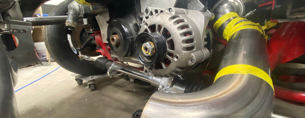


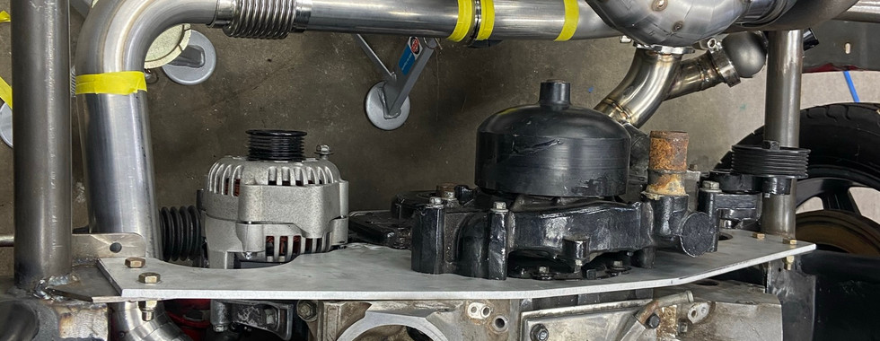


With the first section of exhaust in place, I wanted to get started on the piping to the turbine inlet. I went with the headers offered from CX Racing. This decision was made based on the location of the header outlet. The outlet was back further from the front of the engine compared to the jet boat looking headers people usually use. I wanted to keep the alternator mounted down low, so had to do some more pie cuts to keep the turbine inlet tubing away from it. Knowing the 4" exhaust would be a straight shot out the sides, I wanted to keep the 2.5" piping as tight to it as possible to consolidate the heat. The accordion looking things are bellows sold by Vibrant to absorb any sort of vibration in the piping that could leads to cracked welds later on. They also offer a bit of flex in the piping to make assembly easier.
Quick Pause on the Hot Side to Ensure I'll Be Able to Steer


The ability to identify a future problem is crucial when you are building a car like this. With the turbine inlet piping coming together I quickly realized I was going to have an issue connection the rack and pinion to the steering column. So, that had to be sorted out before I could move forward. The answer was the additionally Steering Shaft U-Joint. In order to run a third U-Joint, the shaft needs to be supported with a Steering Shaft Support Bearing. This just keeps the shaft from flopping around while spinning.
The steering column is from Motion Raceworks and is designed to be cut to fit. So, I took the time to cut it down short and add a Column Extension on the quick release to make getting in and out of the car easier.
Back to Building the Hot Side


With the completed turbine inlet mocked up with the trusty tape, I began tack welding all of the pieces together. I purposely left the bends where the wastegates would be mounted for last so I could take care of the wastegate merge when it was still a small section of tubing.
The job of the waste gate is to direct air flow AWAY from the turbine inlet in order to control the speed of the turbine wheel, therefore the speed of the compressor wheel, and ultimately the amount of air being pushed to the engine.


After a few more (hundred) hours of practicing with the TIG, it was time to do the final welding on the turbine inlet tubing. Here are some examples of those final welds. I am by no means a professional, but my skills had come a LONG way over the time since we got the welder.


Above, you can see photos of the turbine inlet piping and wastegate inlet done. To finish the hot side, I still needed to run the exhaust from the turbine outlet out the fenders. I figured the big pie cut section would be the first thing everyone looks at, so I put off doing final welds on that.


Next, I had make the tear drops and cut the fenders to match.
The existing hole in the passenger fender had to be reshaped to match the teardrop, and a new hole in the driver side fender had to be cut. I used my Rotary Tool to cut the fender because I did not have my Die Grinders at the time. It obviously worked, but I'd recommend using the die grinder because it will cut faster and create less heat lessening the chance of damaging the paint. When cutting or drilling through paint it's always good to lay masking tape first to stop the paint around the cut from peeling up and chipping.


Here you can see the exhaust piping done and out the fender. It sits pretty much flush with the fender when the fender is aligned correctly. I added v-bands to both fender exits to keep things simple to work on as well.


For the wastegate dumps, I was originally a bit hesitant to also put them out of the fender because of the craziness necessary to route them in front of the bigger tear drops. I considered dumping them to the ground but had the realization that if I had an engine failure that dump could end up oiling down the track in front of my rear tires.


Some more final welds on the exhaust.


Finally, it was time to weld the big pie cut section.


Here you can see I added hangers to the exhaust. The colorful stainless welds are cool, but I learned that over time they don't look so good. I used a 3m Bristle Roloc Wheels on my sander/polisher (because I didn't have my Right Angle Die Grinder yet) to clean it all up.


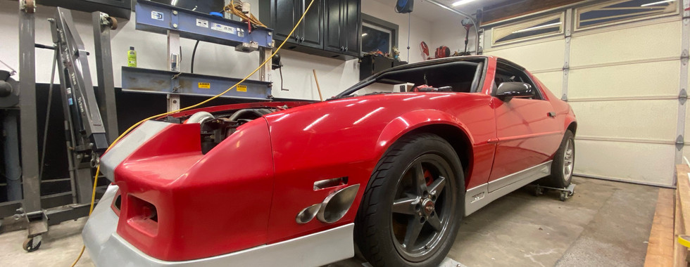
Here are some photos of the completed hot side.
Looking back, I absolutely over complicated what I was doing with the way I wanted things. However, in the end I couldn't be happier with how it looks.
Comments